


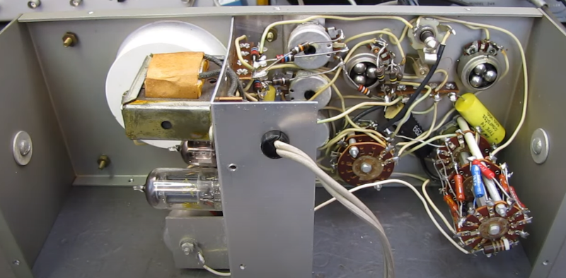
 If you are under a certain age, you might not know the initialism VTVM. It stands for vacuum tube voltmeter. At first glance, you might just think that was shorthand for “old voltmeter” but, in fact, a VTVM filled a vital role in the old days of measuring instruments. [The Radio Mechanic] takes us inside a Heathkit IM-13 that needed some loving, and for its day it was an impressive little instrument.
Today, our meters almost always have a FET front end and probably uses a MOSFET. That means the voltage measurement probes don’t really connect to the meter at all. In a properly working MOSFET, the DC resistance between the gate and the rest of the circuit is practically infinite. It is more likely that a very large resistor (like 10 megaohms) is setting the input impedance because the gate by itself could pick up electrostatic voltage that might destroy the device. A high resistance like that is great when you make measurements because it is very unlikely to disturb the circuit you are trying to measure and it leads to more accurate measurements.
We take that for granted today, but a typical voltmeter in the old days was just a meter with some resistors in front of it. While a good meter would have relatively high resistance, it wasn’t as high as a FET. However, with a tube amplifier, a VTVM could also show a very high resistance and still make good measurements. The Heathkit meter used a dual tube as an amplifier along with some input resistor dividers to provide an 11 megaohm input. There was also a rectifier tube switched in to make AC measurements. In the end, the amplifier drove a conventional analog meter, but that load was isolated from the device under test so its relatively low resistance wasn’t important.


More Stories
via the ARRL: DXer and DXpeditioner Kan Mizoguchi, JA1BK, Silent Key
via the ARRL: The ARRL Solar Update
via the ARRL: New ARRL Santa Clara Valley Section Manager